Fixed-Wing Autonomy
A small RC aircraft turned into a GPS-navigating autonomous platform on INAV: flight controller, GPS/compass, ELRS link, elevon mixing and onboard logging, brought up from bench to flight. Manual flight and autopilot heading hold are flight-tested; autonomous loiter is configured but not yet flown. A side project at Formlabs with CEO Maxim Lobovsky, who did the mechanical engineering on the airframe; I did the avionics and integration.
Overview
This started as a small side project at Formlabs with CEO Maxim Lobovsky. The goal was to take a flying-wing RC aircraft and turn it into a GPS-enabled autonomous platform that can circle a fixed point on its own.
| Maxim Lobovsky | Mechanical engineering: the airframe design |
| Me | Avionics and integration: electronics, flight controller configuration, radio link, sensors, logging and flight modes |
My side of the work was integration: configuring the flight controller for an elevon layout, bringing up GPS and compass hardware, setting up the ELRS control link, validating everything on battery power rather than only over USB, and debugging several cases where the aircraft behaved correctly on the bench but not in its flight configuration.
Results:
- Flight-tested: stable manual flight over ELRS, a 3D GPS fix, and onboard Blackbox logging of navigation and control data.
- Flight-tested: autopilot heading hold under PID control. It held heading, though some PID tunings oscillated.
- Configured, not yet flown: autonomous loiter around a fixed point, switched on from the transmitter.
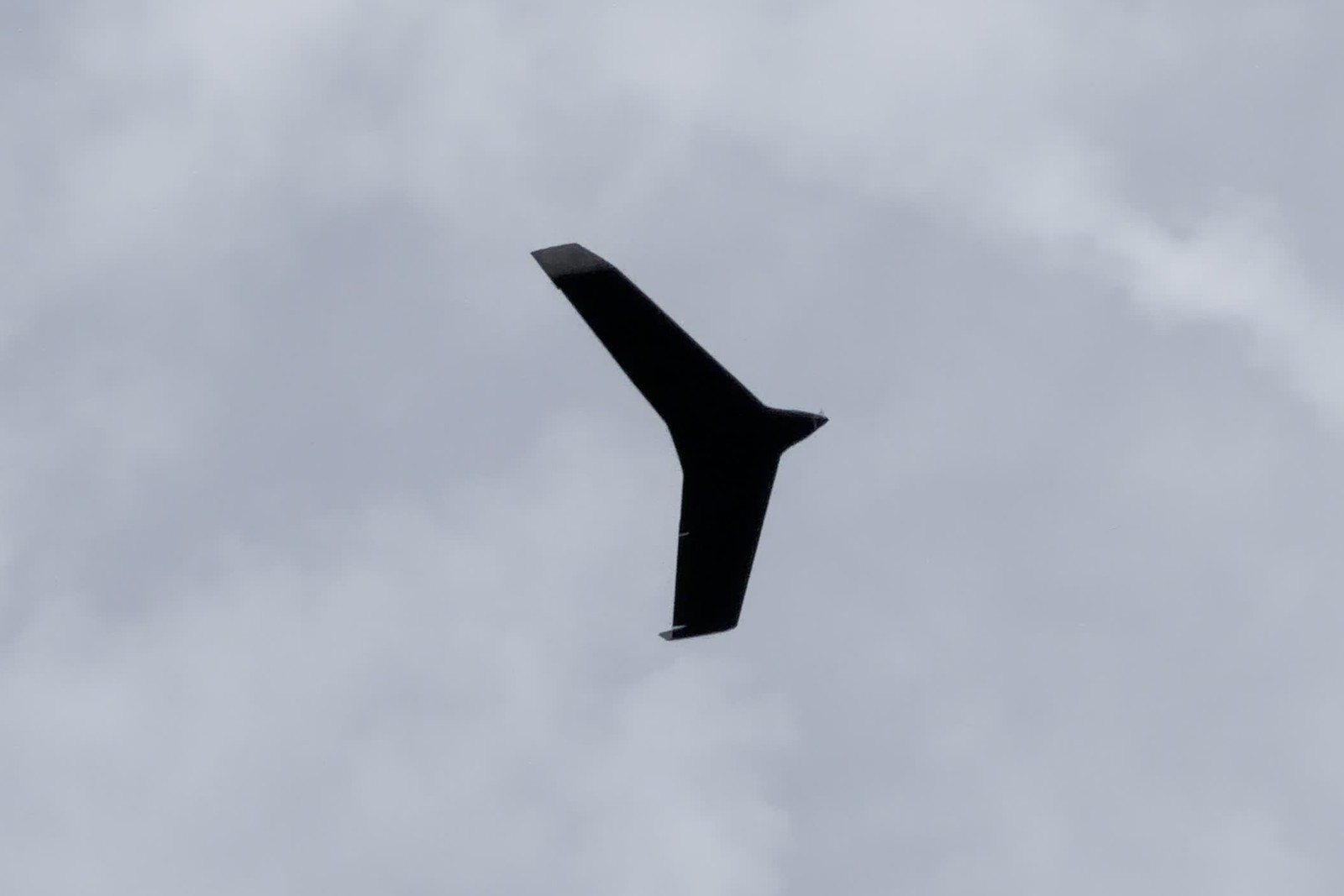
Flight-day pass and turn.
Flight Hardware
The electronics are built around an STM32F405 flight controller running INAV:
- STM32F405 fixed-wing flight controller
- SEQURE M10-25Q GPS module
- QMC5883P magnetometer
- RadioMaster RP1 2.4 GHz ELRS receiver and RadioMaster Pocket transmitter
- Two servos driving the elevons
- 30 A brushless ESC on a 4S battery
- MicroSD card for INAV Blackbox logging
The GPS and magnetometer share one module but use separate interfaces: UART for GNSS data and I2C for the compass. Once both were configured, INAV detected the GPS and the QMC5883P and produced a 3D position fix.
Flight Control Setup
The aircraft has two control surfaces that each combine pitch and roll. In INAV I set up the mixer so each servo gets the right mix of elevator and aileron input, while throttle stays on the motor output.
The ELRS receiver carries manual control and mode channels. I mapped transmitter switches to flight modes so autonomous behavior can be engaged without giving up the ability to drop straight back to manual control.
Before any autonomous flight, I validated the system one layer at a time:
- RC channel mapping and transmitter failsafe
- Servo direction and neutral position
- Pitch and roll mixing
- Motor direction and throttle response
- Accelerometer and compass calibration
- GPS acquisition and position lock
- Mode switching and arming behavior
Bringing it up in stages made it possible to tell an airframe or wiring problem apart from a configuration problem inside the flight controller.
Debugging Battery-Only Behavior
The hardest failure only showed up with USB disconnected.
On the bench over USB, the receiver channels and servo outputs behaved normally. On the flight battery, connecting the transmitter could drive the control surfaces aggressively, and at one point the servos stopped responding even though INAV showed the RC input channels moving correctly.
Because INAV still saw correct RC input, the radio link was fine. That narrowed the fault to the path between receiver input and the servo mixer. The fix was an INAV output setting that explicitly allowed servo input to reach the configured outputs.
A separate USB connection failure first looked like a flight controller problem but turned out to be the USB extender. Both issues came down to the same habit: check each layer on its own instead of treating the flight controller as one black box.
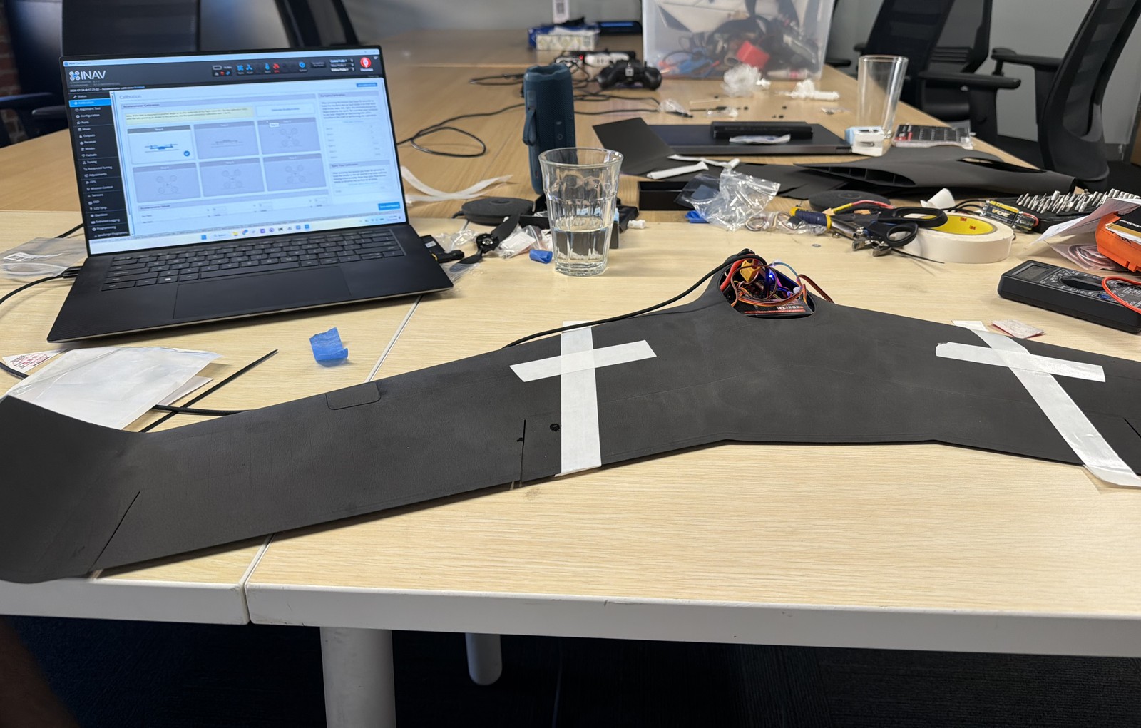
Bench bring-up in the INAV configurator.
Autopilot and Loiter
With manual flight stable, I configured INAV’s navigation stack. The M10 receiver provides position and the QMC5883P provides heading; with the compass calibrated and a valid fix, INAV can estimate position and heading well enough to enable navigation modes.
Heading hold (flight-tested). In flight, the autopilot held heading under PID control. Some of the PID tunings I tried produced oscillation, so the navigation gains still need tuning.
Loiter (configured). Loiter is set up on a transmitter switch: when engaged, the flight controller takes over the control surfaces and throttle to circle a target position. It hasn’t been flown yet.
INAV won’t arm with some navigation modes already active, so the operating sequence is deliberately simple: arm in a manual-compatible mode, establish stable flight, then engage the autonomous mode once airborne.
Flight Logging
I set up INAV Blackbox logging to record the aircraft’s state and the navigation controller during flight:
- GPS / navigation position
- Navigation PID data
- Magnetometer and accelerometer measurements
- Attitude
- RC input and RC commands
- Motor and servo output
Logs are written to the onboard SD card whenever the aircraft is armed, so after a flight I can see what the controller believed the aircraft was doing, rather than relying only on what it looked like from the ground. The same logs are what the heading-hold oscillation will be tuned against.
What I Learned
The useful part wasn’t any single component. It was integrating several independent systems whose failures look nearly identical from the outside: radio configuration, servo mixing, flight controller state, sensor initialization, power behavior and navigation logic. Bench behavior over USB wasn’t a reliable stand-in for flight configuration on battery.
Next Steps
- Tune the heading-hold PID gains from Blackbox data to remove the oscillation.
- Flight-test loiter, then measure loiter radius and path-tracking error.
- Test return-to-home.
- Fly longer autonomous legs in varying wind.
- Compare commanded and measured trajectories from the logs.