PCB Business Card
An interactive PCB business card that combines low-cost hardware design with embedded firmware to create a pocket-sized demo platform. The card integrates an NFC interface, an 8×8 LED matrix, and a Bosch BMA400 accelerometer, using a coin-cell-powered microcontroller to drive tilt- and shake-responsive visual effects such as a gravity-based “sand” simulation. Designed to showcase manufacturable PCB layout, sensor integration over I2C, GPIO-multiplexed displays, and system-level tradeoffs in power, cost, and form factor.
Overview
This project explores the design of an interactive PCB-based business card, serving both as a functional personal identifier and as a platform for experimenting with low-cost, low-power embedded systems. The primary goal is to create a business card that is inexpensive to manufacture, thin, and power-efficient, while still offering a compelling interactive experience.
The current target feature set includes NFC-based portfolio access and a small orientation-aware LED display simulating granular motion (“sand”) within an 8×8 matrix.
Inspiration
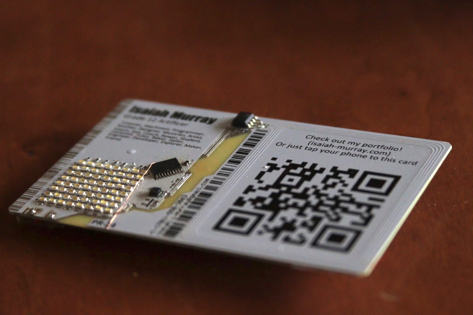
Interactive PCB business cards are a well-established concept within the hardware community. This project is inspired by prior work in the space, with a particular focus on achieving a comparable level of polish while emphasizing manufacturability, cost control, and component availability.
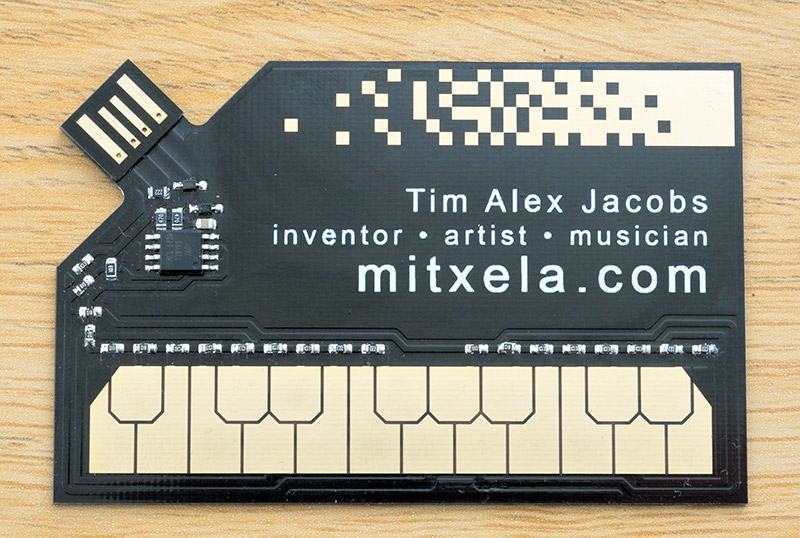
A high-quality reference design by Tim Jacobs (mitxela.com), which integrates MIDI functionality into a PCB business card.
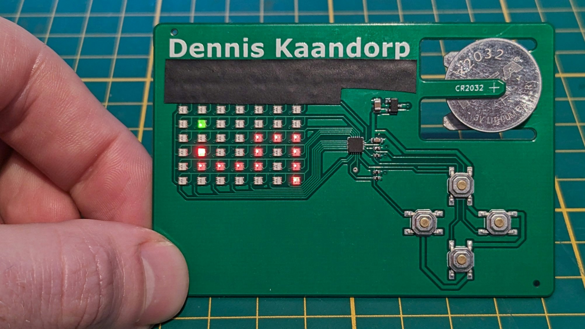
A conceptually similar LED-based business card encountered during development, reinforcing common design constraints and tradeoffs in this form factor.
System Architecture
The card consists of four primary subsystems:
- NFC interface
- LED matrix display
- Inertial sensing (IMU)
- Coin cell power source
NFC Interface
The NFC subsystem is intended to expose a simple NDEF payload—specifically a URL pointing to my portfolio—when scanned by a nearby smartphone. I am also exploring partial passive operation so that basic NFC functionality remains available even if the onboard battery is depleted or not installed.
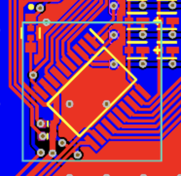
In the first design iteration, the NFC antenna traced the full perimeter of the PCB. While this provided uniform coupling, it significantly constrained ground routing and increased interference risk.
In the second iteration, the antenna was isolated to a dedicated region occupying approximately half of the card, with the remaining area reserved for logic and power circuitry. This separation reduced ground-plane interference and simplified routing.
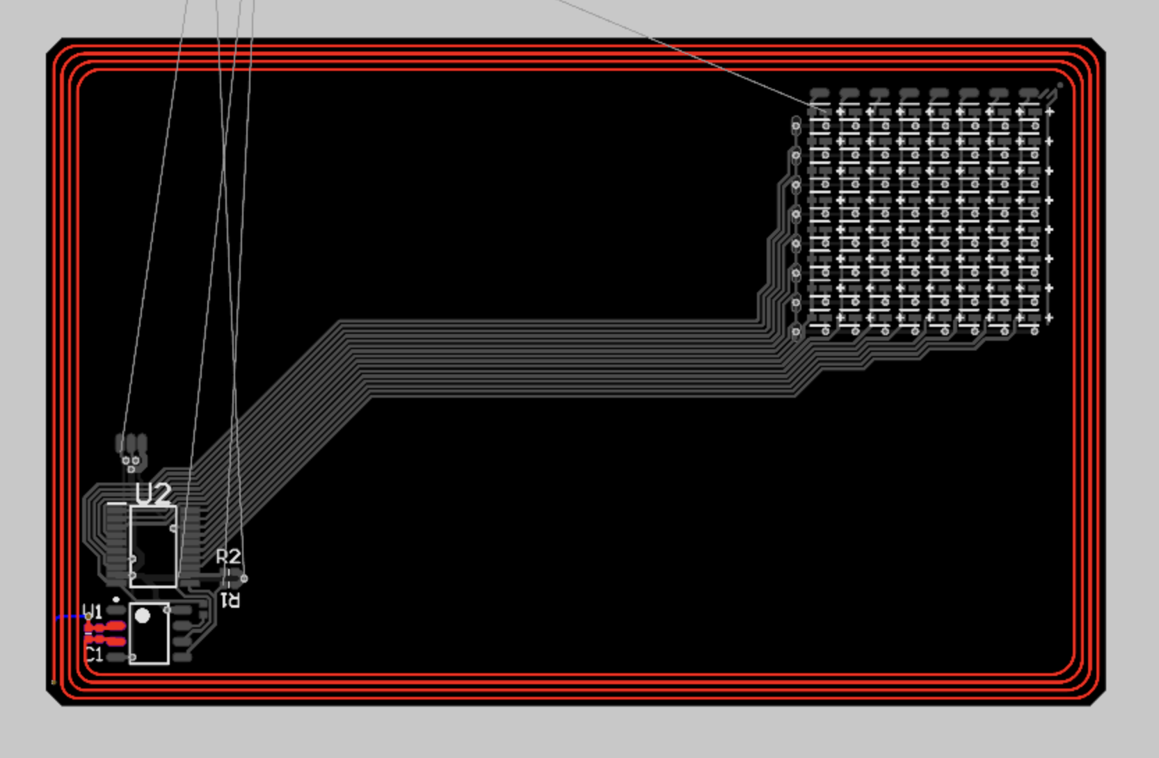 Iteration 1: Perimeter-traced NFC antenna
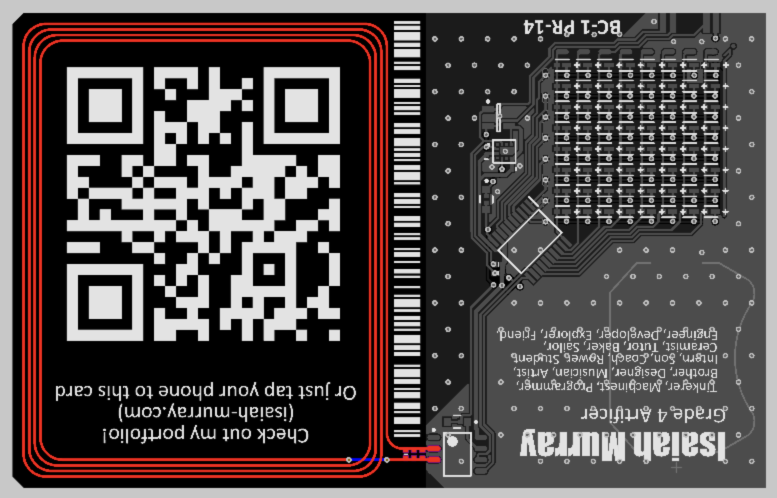 Iteration 2: Dedicated antenna region
LED Matrix Display
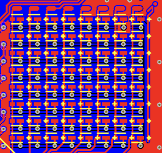
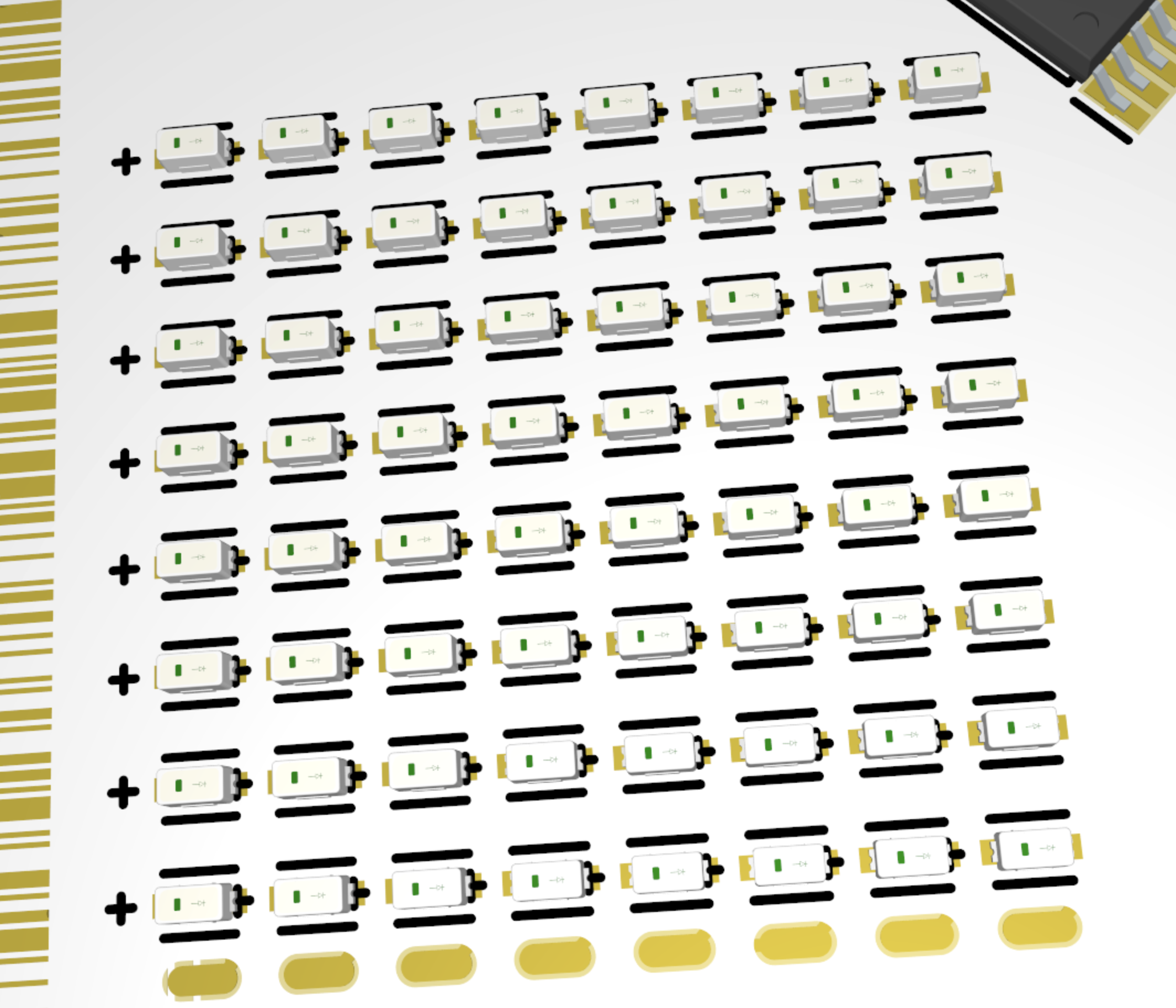
The LED matrix serves as the primary visual output. The display consists of an 8×8 common-cathode matrix, totaling 64 LEDs.
Early designs targeted 0201 footprint LEDs to maximize pixel density. However, due to cost, yield concerns, and current draw, the design transitioned to 0603 low-current LEDs. The selected LEDs draw approximately 0.5 mA per LED, significantly improving power efficiency relative to earlier candidates rated closer to 20 mA.
Depending on real-world brightness and power performance in the first prototype, future revisions may explore smaller footprints or dual-color LEDs to increase visual depth without substantially increasing complexity.
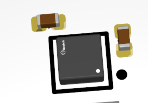
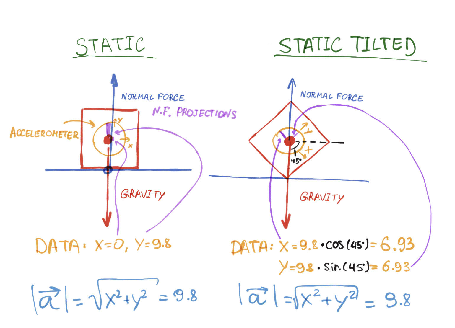
Inertial Measurement Unit (IMU)
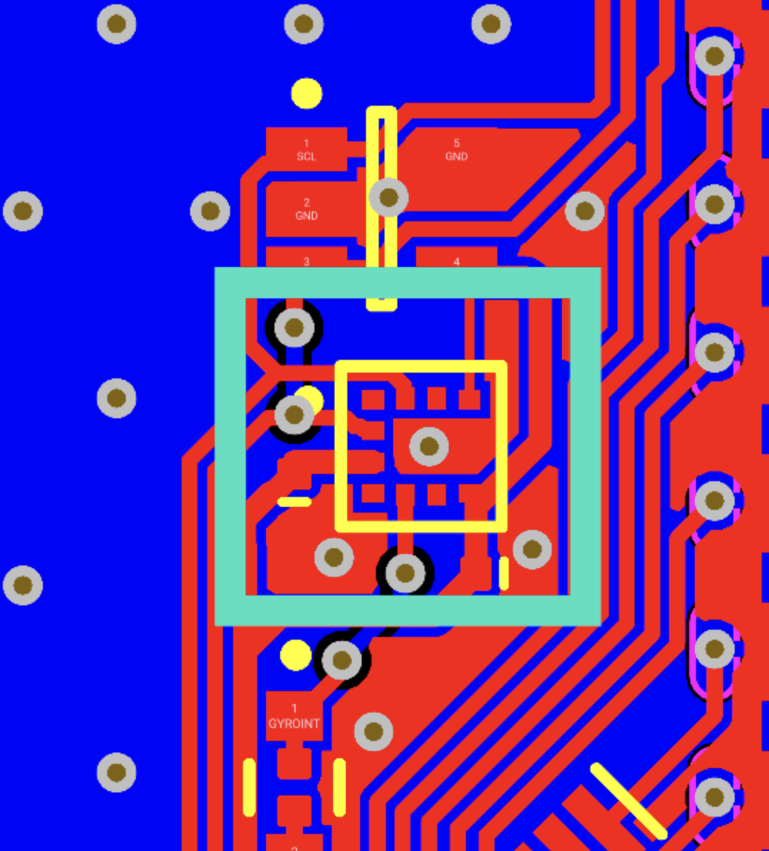
Orientation sensing is used to provide a gravity reference for the LED “sand” simulation. Early component searches focused on MEMS gyroscopes, under the incorrect assumption that they directly provide absolute orientation. After recognizing that gyroscopes measure angular velocity rather than orientation, attention shifted to accelerometer-based solutions.
High-precision IMUs were initially considered but quickly ruled out due to cost constraints. Simpler tilt sensors were also evaluated but rejected due to pin count and lack of direct digital interfaces.
The final selection was the Bosch BMA400, a low-cost, low-power 3-axis accelerometer capable of measuring gravity vectors with sufficient resolution for orientation estimation. The device supports I²C communication and interrupt generation, making it well-suited for this application at approximately $2 per unit.
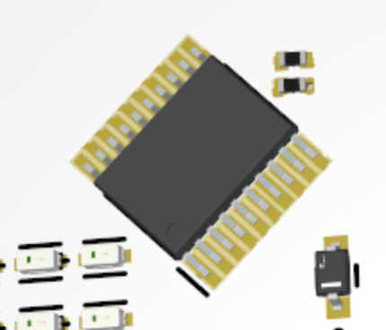
Microcontroller
The system controller is the CH32V003F4P6, a low-cost 32-bit RISC-V microcontroller operating at up to 48 MHz with 2 KB SRAM and 16 KB flash. Despite its small footprint and low price, it provides a useful peripheral set including ADC, I²C, SPI, USART, and single-wire debugging support.
This device was selected over more traditional 8-bit microcontrollers due to its favorable performance-to-cost ratio and modern toolchain support. Its low-power modes make it appropriate for coin-cell-powered operation.
Power Source
Power availability was a major constraint influencing feature selection. Several options were evaluated:
- Unpowered: NFC-only functionality
- Thin-film lithium: Extremely low capacity, NFC-harvest recharge
- LiPo: Rechargeable but costly and circuit-complex
- Coin cell: Inexpensive, readily available, moderate capacity
The final design uses a coin cell battery to balance cost, simplicity, and usable current capacity without introducing charging circuitry.


Conclusion
This project demonstrates iterative PCB design, component tradeoff analysis, and system-level engineering under real manufacturing constraints. While still in progress, the core architecture—NFC-based identity, orientation-aware LED display, and ultra-low-cost control hardware—has been validated at the schematic and layout level.
Future work includes firmware optimization, power profiling, and mechanical refinement for durability and manufacturability. The project serves both as a functional personal artifact and as a compact demonstration of embedded hardware design skills.
Repository: https://github.com/LoveAsAConstruct/Business-Card