Radar Calibration Automation
An internal calibration automation project focused on phased-array radar systems. The work replaced manual antenna gain and phase tuning with a programmatic workflow driven by FPGA control, spectrum analysis, and algorithmic optimization—reducing calibration time from hours to minutes while significantly improving array efficiency.
Overview
This project was completed at Cherish and focused on automating the calibration of a multi-antenna radar system. Prior to this work, newly fabricated boards required manual tuning of antenna gain and phase, a time-consuming process due to the number of antennas on each board.
The objective was to replace this manual workflow with an automated calibration program capable of rapidly tuning transmit and receive antenna arrays while improving overall radiation efficiency.
My Involvement
When I joined the project, the hardware team was actively seeking ways to automate antenna calibration. I took ownership of the problem and designed a software-driven approach to calibrate both the transmit (TX) and receive (RX) arrays.
The radar system consists of two antenna arrays:
- A transmit array
- A receive array
These arrays are controlled by four beamformer chips:
- One beamformer for the transmit array
- Three beamformers for the receive array
All beamformers are controlled by an onboard FPGA, which I interfaced with from a PC to configure phase and gain settings programmatically.
Calibration Strategy
I approached the problem in two phases:
- Transmit array calibration
- Receive array calibration
Each array required a distinct methodology due to differences in signal flow and measurement constraints.
Transmit Calibration
Each antenna element in the transmit array has configurable gain and phase.
- Gain controls signal power output.
- Phase offsets the transmitted sine wave to enable beamforming.
Gain Calibration
To calibrate gain:
- I used the FPGA to read the power draw of each antenna.
- A reference antenna was selected.
- Other antennas were adjusted to match the reference power level.
Legal emission limits imposed a lower bound on attenuation to ensure regulatory compliance.
Phase Calibration
Phase calibration was more complex due to manufacturing variability in trace length and PCB material.
The procedure:
- The board was placed inside an RF isolation enclosure.
- A spectrum analyzer measured signal strength at a fixed receiver.
- Each antenna was iteratively phase-shifted to minimize received power.
Minimizing power avoids distortion from radiation-pattern lobes that scale with signal amplitude. Once the minimum was found, the antenna phase was flipped by 180°, aligning it with the reference signal without amplifying lobe artifacts.
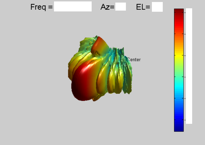
After calibration, I measured the transmit radiation pattern by rotating the board in fixed angular increments and recording signal intensity. This data was plotted as a radar chart to visualize beam distribution.
An initial attempt at gain calibration used an aggressive simulated annealing approach, which overfit antenna gains to board geometry and degraded real-world performance. Switching to a gentler approximation strategy produced a significantly cleaner radiation pattern.
Receive Calibration
Receive calibration differed due to the architecture of the RX array.
- Antennas were split across three beamformers, each controlling a subset of elements.
- Each subset was first locally phase-calibrated using the same minimization approach as the transmit array.
After local calibration, the three receiver arrays were phase-misaligned relative to each other. While each array performed well in isolation (up to 142% improvement), they interfered destructively when combined.
The issue was traced to a configuration override that unintentionally bypassed global phase offsets. Once global offsets were applied directly at the antenna level, receiver performance improved dramatically.
This final approach resulted in a 310% increase in received power.
.png)
Results
- Reduced calibration time from multiple hours to a ~30 minute automated program.
- Improved antenna efficiency by up to 310%.
- Delivered consistent, repeatable calibration results across boards.
- Eliminated a major manual bottleneck in radar hardware bring-up.
Takeaways
- Automated calibration is essential for scaling phased-array radar production.
- Minimization-based phase alignment is more robust than direct maximization in the presence of radiation-pattern irregularities.
- Over-aggressive optimization can degrade real-world performance despite good simulated results.
- Tight integration between FPGA control, RF measurement equipment, and software tooling enables substantial efficiency gains.