Radar Calibration
This is a project I worked on within Cherish. Previous to my involvement, the hardware department would receive boards from fabrication, and have to calibrate the antennas gain and phase by hand. There are many antennas on the board (exact number cannot be disclosed) so this process was taking a while.
My Involvement
When I joined, people were looking to automate this process. Hoping to speed up the process, I began to try my hand at the issue.
There are two antenna arrays, one for transmitting signals, and one for receiving signals. These arrays are controlled by a total of four beamformer chips, one for the transmit array, and three for the receive array. These beamformer chips are in turn controlled by the onboard FPGA, which I connect to through a PC.
I decided to approach the problem of calibration in a two pronged approach, I would first calibrate the transmit array, and then calibrate the receive array. To calibrate the transmit array, I needed to use a spectrum analyzer to process a signal outputted by the board. This was directly contrasting the receive array, which used a signal generator to emit a wave that could be processed by the antennas.
Transmit Calibration
This was the first array I calibrated. Each antenna on the array has a phase and gain. The phase is responsible for offsetting the signal received by the beamformer, causing the antenna signal to be delayed by a specified amount. The gain effects the power of the signal, with more gain (attenuation) lowering the power output.
To calibrate the gain of the antenna, I would utilize the FPGA to read the power draw of each antenna, and after choosing a reference, modify all other chips to match that set power level. Due to legal guidelines, I would have to ensure that the gain was above a value to keep the signal range being emitted below a legal limit.
The calibration of phase was a bit harder. Each antenna outputs a sine wave, offset slightly based on the trace distance and board material of the circuit, which differs by manufacturer. Due to this, I need to sync up the sine waves to maximize the power being read by a spectrum analyzer. The board is placed within a RF isolation box, and pointed towards a receiver at the other end of the box.
Once the RF array is setup within the box I loop through each antenna connected to the beamformer, and, critically, find a phase value that minimizes the signal strength on the spectrum analyzer. I minimize the value due to the existence of radiation pattern irregularities, which manifest as inconstancies in each antennas signal strength distribution. This causes abnormal “lobes” of high or low energy to appear on the fringes of an antennas radiation, and scale in severity along with the power of the antenna. Due to this, we minimize the power, also minimizing the effect of the electromagnetic lobes, and putting the antenna directly out-of-phase of the overall signal. The antenna’s phase is then completely flipped, which puts the antenna alongside the phase of the reference, without causing anomalies due to radiation pattern irregularities.
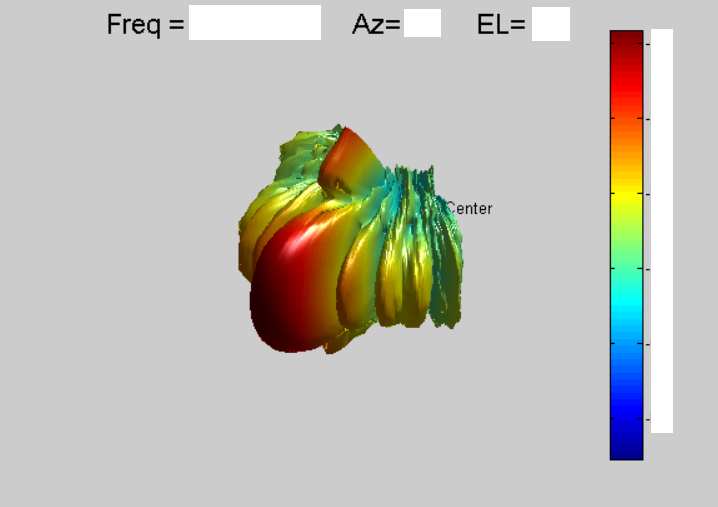
Once this was calibrated, I analyzed the transmit signal distribution with a radar plot, where I would rotate the radar board by a specified interval, and take another sample, gradually accumulating the signal intensity from each angle of the board. The resulting graph showcases the signal distribution of the phased radar array.
Unfortunately, the graph showcased A slightly non-ideal radiation pattern. After much frustrated debugging, it was determined that the result of this was from the gain calibration, as each antenna starts with acceptable gain, and the simulated annealing algorithm is much to vigorous, overfitting the antenna gain to the geometry of the board, resulting in less-than-optimal performance of actual signal transmission.
With the gain calibration passed in favor of a much gentler value approximation, the radar displayed significantly higher quality beam distribution when compared to a non-calibrated, manually-calibrated, or overfitted array.
Receive Calibration
The calibration of the RX arrays was slightly different. Rather than routing all antennas through a single beamformer, the antennas were distributed across three separate beamformers, each responsible for a section of the emitter.
The antennas within each beamformer section began by being locally calibrated to each other. This was done using the same phase-matching function as the transmitter array.
After this local calibration, I was left with three receiver arrays emitting at different phases. This resulted in each array performing well when isolated (142% improvement) but interfering when transmitting as one module.
To solve this problem, I chased a configuration installed in the library to offset each beamformer chip’s phase by a set quantity. However, unbeknownst to me, the override I was using to calibrate the array was inadvertently overriding the initial global offsets. This contributed to a good amount of insanity and pouring over old code.
Eventually, I realized I needed to apply the global offsets directly to the individual antenna arrays. Implementing this resulted in exceptional receiver array performance, and a power increase of 310%.
.BGC1Bjgh.png)
Final receive array azimuth distribution (censored)

Final receive array azimuth and elevation graph (logarithmic)
In the end, I was able to speed up calibration times from many hours of employee time to a 30 minute program, which improved antenna efficiency with up to 310% improvements.
