Canopy
A telemetry, power distribution, and diagnostics system for the Olin Baja Racing car, built around an STM32H743 network supervisor and a CAN bus tying together sensor, power, and telemetry data. Co-developed with Aryan Banerjee and Zach Wheeler.
Overview
Canopy is Olin Baja Racing’s telemetry, power distribution, and control system, maintained by Isaiah Murray, Aryan Banerjee, and Zach Wheeler. Its goal is to centralize data collection across the car and support electronic diagnostics during testing and races.
The system has three main parts: a power distribution board (PDB), a network supervisor board (NSB), and a CAN network connecting them to the car’s sensors. My work on the system has centered on a ride-height suspension sensor for damper tuning and the CAN-based data acquisition side of the diagnostic canopy.
Network Supervisor Board
The NSB is the core of the system, built around an STM32H743ZITx (Arm Cortex-M7, up to 480 MHz, 2 MB Flash / 1 MB SRAM). It manages the CAN network and handles data collection from runs, and is connected to a CAN transceiver, SD card, flash memory, an SPI bus for LoRa telemetry, and an I2C chain carrying a temperature sensor and accelerometer. It also exposes a Cortex-M SWD debug header and a USB connector for wired runtime communication.
Data collection and transmission — the NSB operates in either a recording or passive state, with four available data paths depending on what’s connected:
- If a computer is connected via USB, the NSB streams CAN packets regardless of recording state.
- If the LoRa transmitter is connected and enabled, CAN packets stream over LoRa regardless of recording state.
- If an SD card is inserted, CAN packets are logged to the card in CSV format while recording, timestamped per session.
- If none of the above are available while recording, the NSB falls back to onboard memory at a reduced rate and raises a status-LED warning.
Recording state and active storage medium are themselves published onto the CAN network, alongside all other telemetry.
Logged CAN data:
| Module | Data | Type | Rate | Priority |
|---|---|---|---|---|
| Hall Effect | RPM | Int | 100 Hz | 1 |
| Ride Height | Activation % | Float | 50 Hz | 2 |
| GPS | Position | Vector2 | 5 Hz | 3 |
| Wheel | Record Instance | Event | — | 2 |
| Wheel | Highlight | Event | — | 2 |
| NSB | Network Overhead | Float | 1 Hz | 5 |
| NSB | Record Status | Bool Array | 0.1 Hz + Event | 3 |
| NSB | LoRa Status | Float | 1 Hz | 3 |
| PDB | Circuit Load | Float | 10 Hz | 4 |
| PDB | Battery Status | Float | 0.1 Hz | 5 |
Power Distribution Board
The PDB regulates and distributes power to every component on the car, drawing from the battery and tethering through the NSB onto the CAN network as a sensor node. It provides auxiliary rails at 12V, 5V, and 3.3V, and also handles the high-sensitivity power rails feeding the NSB. This board is spearheaded by Aryan Banerjee and is still in progress.
CAN Communication Subsystem
The MCU’s CAN2 lines route to an MCP2561-E-SN transceiver, which converts the STM32’s single-ended TX/RX signals to differential CANH/CANL bus levels (ISO 11898-2, up to 1 Mbps). Bus protection includes a Würth WE-CNSW common-mode choke and NUP2105L dual-line TVS/ESD diode arrays on the CAN lines, with a 3-pad solder jumper allowing hardware or software control of the transceiver’s standby line.
Hardware Iterations
The build has moved past the schematic-level documentation above and is now on physical hardware, with a separate power supply board providing power to the NSB system:
- Prototype board — an early NSB prototype, essentially an STM32H7 dev-kit-style board, used to validate the core design before laying out a dedicated PCB.
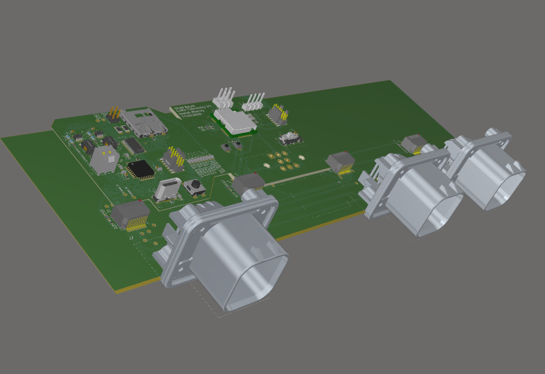
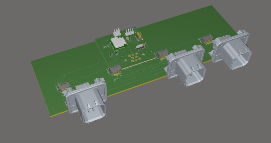
- Carrier board (v2) — a second-iteration board that routes communication from a series of slot connectors to the edge-connector types used on the car.
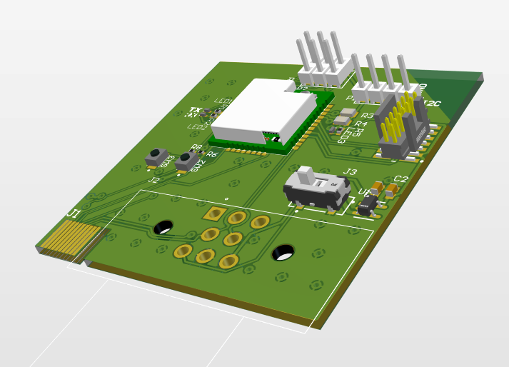
- LoRa add-on board — plugs into the carrier board for wireless telemetry. It can also run standalone, and breaks out pads to solder on a waterproof connector when the antenna needs to sit away from the compute enclosure.
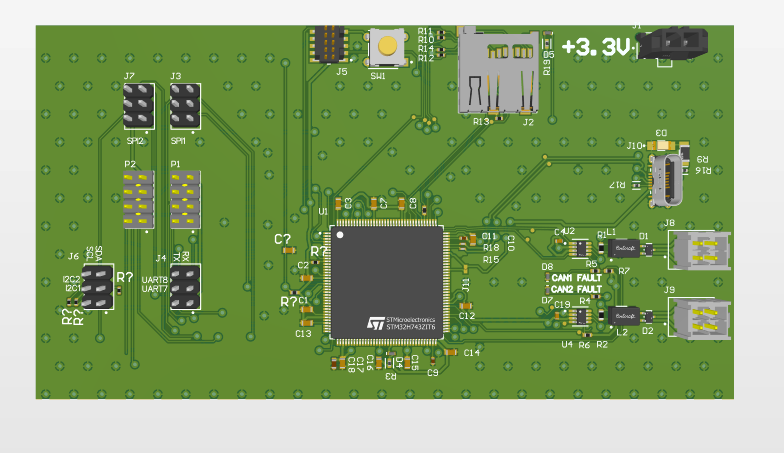
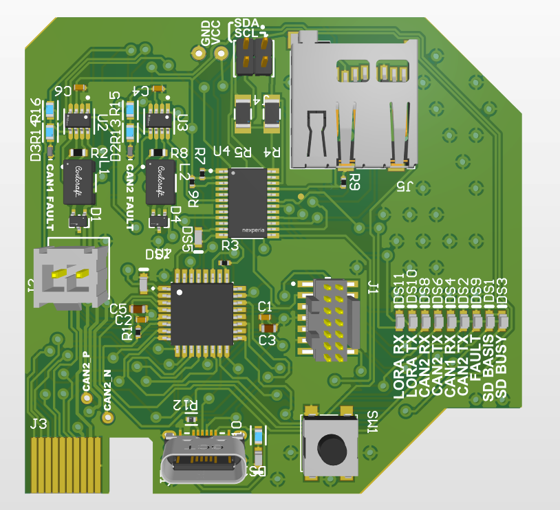
- Compute card — carries the SD card, CAN buses, status LEDs, and the STM32 MCU.
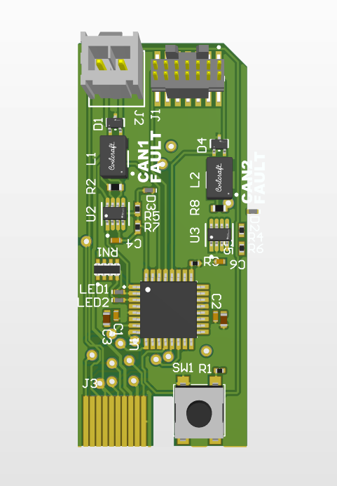
- Compact card — a smaller revision of the compute card that trims the status/debug hardware down for a tighter footprint.
Design Status
This is an active, in-progress design, now in hardware across the iterations above. Open items the team was tracking as of the last schematic review: confirming discrete regulator stages for the 3.3V rails, adding a termination resistor across CANH/CANL, defining the LoRa module’s interface pins and antenna path, and implementing the USB and SWD debug connectors.
Media
Prototype board — an STM32H7 dev-kit-style board used to validate the core NSB design.
Carrier board (v2) — routes communication from slot connectors to the car’s edge-connector types; shown here with both the compute card and LoRa board attached.
LoRa add-on board — plugs into the carrier board for wireless telemetry, or runs standalone with pads for a waterproof antenna connector.
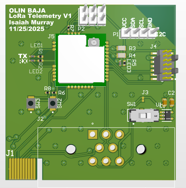
Compute card — SD card storage, dual CAN buses, status LEDs, and the STM32 MCU.
Compact card — a smaller revision of the compute card with reduced status/debug hardware.